Các bài báo kỹ thuật
Đã xuất bản 07/2019
Distributed Automation IV – Dealing with Protection Grading
Why Sectionalising Functionality is needed in Reclosers

In our last article, Distribution Automation III, we explored the quintessential Ring Mode network design configuration and the automation of switching to isolate faults without the use of communications between the devices. This method of distributed automation relies on sensing voltage presence on either side of the circuit breaker, in this case a Recloser, to determine whether to close to restore power.
Of course, this leads to at least one more reclose onto a fault, but this is mandatory for any communications-free automation scheme. Provided that local electricity policy permits the full three reclose operations stated in the standards, we can use 2 protective recloses from the normal feed method and one close from the automation method and remain compliant.

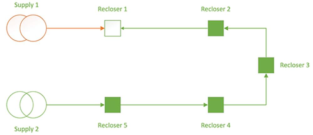
However, this distributed automation configuration within a ring mode does provide unique protection challenges. With a ring mode configuration, there is a real possibility that power flow direction may change depending on switching configuration. Consider the case that Supply 1 failed:

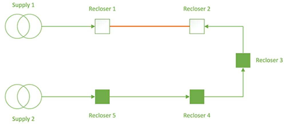
In this case, Recloser 2 now has reverse power flow to standard operation. Therefore, the use of directional protection becomes essential to provide grading. Under normal system configuration, Recloser 2 is the furthest from the substation, closest to the tie point. If supply 2 fails, it becomes the 2nd closest to the substation, with 3 other downstream devices. In the case above, it becomes the furthest recloser from the substation – each case requiring its own protection grading.
A quick reminder, Protection grading is the coordinated configuration of tripping responses so that protection devices coordinate with each other to ensure the minimum zones are impacted by faults. In this case, we have three protection scenarios we need to account for in our grading. We’ll use Recloser 2’s settings as our reference, although this simple situation analysis should be applied to all devices in the scheme for confirming settings.
| Scenario | Diagnosis | Considerations |
|---|---|---|
| System Normal | Fastest tripping device, furthest from the substation | Can be automatically switched to take on the load up to Recloser 5. Therefore, Overcurrent and ratings need to allow for load, and graded up to R5 |
| Supply 2 Fails | 2nd device in chain | Need to grade with R3, R4 and R5 |
| Supply 1 Fails | Last device in chain, power flow reversed | Need to grade in reverse overcurrent with R5 the slowest and R2 the fastest |
Handling the system normal condition is equivalent to standard protection design, except that consideration must be given to the additional load current taken on when the rest of the ring is added if supply 2 fails. This puts a limit on how low the overcurrent setting can be configured at R2 (and it’s counterpart R4 when supply 1 fails).
Therefore, from the perspective of Recloser 2, System Normal and Supply 2 fails require the same protection configuration, at the cost of some sensitivity to overcurrent.
In the case of Supply 1 failing, Recloser 2 needs to have direction overcurrent configured, where it acts faster than R3, R4 and R5. This can be accomplished as standard with a NOJA Power OSM Recloser system, configuring the directional overcurrent to grade appropriately in this scenario.

Handling Insufficient Grading Margins
Configuring the protection for these automation cases is generally straightforward, provided that there is sufficient grading margin.
In the case that the substation breaker is set to trip at 1 second of max fault current, grading margins of 250ms between coordinated devices would allow for a maximum of 4 reclosers along the line. Whilst 250ms is conservative by modern recloser standards (150ms grading is comfortably reliable with modern equipment), it does limit the number of protective devices that can be switched in.
Unless the devices switched in are Sectionalisers.
If we consider the case of figure 3, but let’s assume a more conservative grading margin of 300ms with a 1 second substation breaker time, we can only fit 3 protective reclosers in before the substation would trip. Under system normal, this would be easily handled, but adding the two extra reclosers during an automation operation (R3 and R2), a race condition will be created if a fault occurs between R1 and R2.
But if R2 is configured to operate as a sectionaliser in the reverse current flow direction, its response becomes determinate and it can be graded with the rest of the system. R2 then acts as a normal recloser in the System Normal and Supply 2 Failure cases, but under the Supply 1 Failure case it will allow fault passage and open in the dead time of the upstream breaker.
By having the Recloser act as a sectionaliser in the reverse power flow condition, we can be assured that the risk of mal-grades are mitigated.
A quick note on Load Insensitive Protection
When building these automation networks, using Load Insensitive Protection such as Negative Phase Sequence Protection or Earth Fault Protection becomes highly desirable. These features respond to network imbalances, and whilst they are not used for symmetric faults, 90% of network faults are asymmetric and will be detected by NPS and EF at much lower current levels before Overcurrent would pick up.
Conclusion
Smart Grid Automation achieved using distributed logic based on voltage presence is a highly reliable, cost effective method of implementing the smart grid. Without needing communications, it is possible to effectively re-switch the network to isolate faults, and in this article we explored some of the technical considerations required for designing protection settings for these automatic switching networks.
By using a scenario method, evaluating the required protection settings becomes generally straightforward, with a few constraints based on the amount of load that could plausibly be added. These are generally considered when ring mode networks are designed originally, however it is worth revisiting the protection settings when developing an automation scheme.
Using Reclosers that have a sectionaliser function provide an effective technique for deploying automation within limited grading constraints.
And lastly, we also gave a quick mention of Load Insensitive protection, such as NPS, as a possible solution for maintaining sensitivity despite large variances in load which can occur in these automation schemes. A quick overview of NPS is available "Demystifying Negative Phase Sequence Current Protection"
“These articles demonstrate that our recloser control is DA ready standard. Whether you use the built in automation algorithms, use the built in sectionalising functionality or the IEC61499 smart grid automation that allows you to write your own logic between multiple devices in the network, our recloser controls provide the building blocks to do that.”
Which brings us to the theme of our forthcoming articles – communications-based automation and centralised automations schemes.
Quan tâm đến Công nghệ mới nhất về phân phối điện năng?
Hãy tham gia vào danh sách nhận các bài viết kỹ thuật hàng tuần, chúng tôi sẽ chia sẻ kinh nghiệm trong nghành kỹ thuật điện toàn cầu trực tiếp đến hộp thư của bạn
Đăng ký →