Các bài báo kỹ thuật
Đã xuất bản 07/2019
Automation III – Distributed Automation
Building a Smart Grid, without Communications

In edition one of our series, we covered the fundamental case of automation of the distribution network – a simple Auto-Changeover Scheme using the voltage sensors on either side of a NOJA Power OSM Recloser and some simple control logic to detect what to do. This greatly effective technique allows for automation of power supply changeover for critical loads and provides great reliability when communications infrastructure is not available. Despite the economic value of such a setup, the key drawback was the extra close onto a fault scenario, when the fault is on the load side of the switchgear arrangement.
So naturally, our resolution to this is a single step forward in complexity, integrating a Peer to Peer (P2P) communications link between the devices. This method is arguably the most common form of Automation, so much so that the dedicated feature set of “ACO” in the NOJA Power Recloser system is available as standard in each unit. This system allows for a P2P link between NOJA Power OSM Reclosers to share data on power quality or faults, addressing the two key drawbacks of comms-free schemes:
- Mitigating the risk of closing onto load-side faults and
- Facilitating control of the full automation system at a single location
With this grounding in basic automation cases, we come to this week’s topic.
Automating Ring Networks without Communications
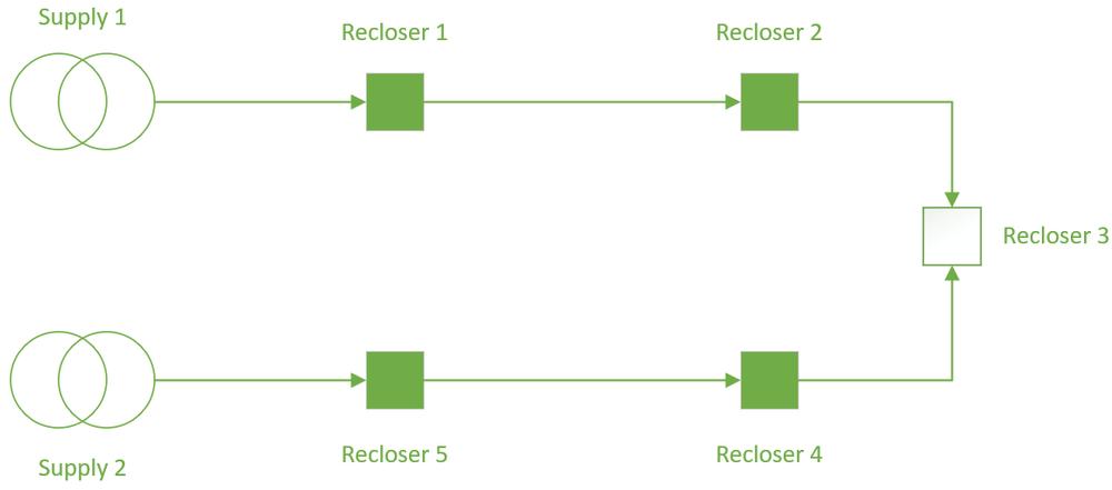
Our first case study demonstrating Smart Grid Automation without communications is a concept that can be applied to the broader grid, with some forethought of the scenarios of network switching that are likely to occur. When considering the design of reliable distribution networks, the “Ring” type network topology is commonly used.

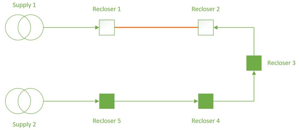
The ring type network allows for effective switching isolation of a faulted feeder, with the tie point, in this case Recloser 3, being closed up to the faulted location. For illustration, let’s say the fault occurs between Recloser 1 and 2, a manually re-switched network isolating the fault and restoring the supply would be thus:

In a manual process, the operator would first note that Recloser 1 has opened due to a permanent fault. The brute force method then is to close the tie point recloser, Recloser 3. Provided protection is appropriately graded for directionality, Recloser 2 would then be the closest unit to the fault, tripping faster than the upstream devices and effectively isolating the faulted section of the line.
When closing onto faults provides a low risk, the brute force method discussed above is the most-simple method to automate. It is functionally similar to the Auto-Changeover scheme without communications discussed in our first article, allowing for improved reliability of supply without communications, but at the cost of one extra close-onto-fault in each restoration. In the event of a loss of supply from one of the substations, no extra close onto fault occurs, and the automation scheme provides better reliability.
How to Implement?
| Source Reclosers | Feeder Reclosers | Tie Recloser | |
|---|---|---|---|
| Reclosers | R1 and R5 | R2 and R4 | R3 |
| Scenario 1: Loss of Supply | Recloser closest to the substation must detect loss of supply, and automatically open to stop a backfeed energisation when the tie point closes | No Action | Detect Loss of Voltage on one side of the open breaker, execute an automatic close to re-energise the network. Should be slower to close than the Isolate Operation from R1 or R5 |
| Scenario 2: Fault in a zone | IF the fault is between the Source and the Recloser, open as per scenario 1, otherwise trip based on grading | Trip based on Grading. Possible Grading Margin issues after close (explored in our next edition, Automation IV) | Detect Loss of Voltage on one side of the open breaker, execute an automatic close to re-energise the network. Should be slower to close than the Isolate Operation from R1 or R5 |
Using the same principle of voltage detection on either side of the recloser explored in topic one, we can apply this logic to the reclosers in a ring scheme to detect and isolate faults rapidly. The only cost in this scenario is that fault conditions will cause one extra close onto fault.
Whilst this may seem like a significant drawback, network standards permit a maximum of 4 reclose operations in a single protection sequence, and with the automation closes having a “one shot to lockout” policy (achievable as standard with NOJA Power OSM Reclosers), you can limit the protection operation sequence to a maximum of 3 reclosers and remain standards compliant, provided that it is not a contravention of local energy distribution rules.
Conclusion
In contexts where communications infrastructure is not sufficiently reliable for automation or an additional close onto fault is permittable, then distribution automation without comms can be a highly effective practice. Whilst this network practice does bring an additional close onto a fault, the economic and reliability gains are exceptional without dependence on communications, making this a highly popular implementation of the Smart Grid.
“This series has demonstrated Automation can be a step by step process investing in the building blocks over a period of years in line with capital budgets available starting with reclosers to protect the network”, reports NOJA Power Group Managing Director Neil O’Sullivan.
In our next edition, we’ll cover the subtleties of protection grading in these ring-mode Smart Grid automation schemes.
Quan tâm đến Công nghệ mới nhất về phân phối điện năng?
Hãy tham gia vào danh sách nhận các bài viết kỹ thuật hàng tuần, chúng tôi sẽ chia sẻ kinh nghiệm trong nghành kỹ thuật điện toàn cầu trực tiếp đến hộp thư của bạn
Đăng ký →